Measuring Pressure Changes With a Spoiler: Part 3

 
This summer, I tested a large spoiler at different angles, with and without fins, by measuring pressures on the rear window and base of a Prius.
 
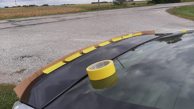
Recently, I tested two variations on this. First, a Gurney flap is a short vertical spoiler placed at the trailing edge of bodywork or an existing wing or spoiler. I made a flap out of cardboard, about an inch high:


Then, after reading about possible beneficial effects from a spoiler with a wavy edge rather than straight, I made another cardboard strip with a sinusoidal shape:


Would there be any difference between the two?
 
Lastly, I took the 20° spacers I had fabricated for my previous test and taped the spoiler board to them, but this time with a slot or opening at the bottom. How would this compare to a spoiler with no slot?


Results
 
As one might expect, the Gurney flaps did not increase pressure on the window as much as the large spoiler. And there was no difference in window or base pressures between the straight-edge and sinusoidal flap:

Measurement locations are the same as in the previous test.

At this point, I have accumulated quite a bit of information on panel pressures with various types of spoilers. As before, window pressures increase but base pressure decreases—this appears to be the general behavior of a spoiler on my car. Now the question is: can I determine which spoiler design is optimal among the choices I have tested so far?
 
A Method for Estimating Drag and Lift Change
 
The answer to that question is: perhaps. Perhaps I can estimate changes in lift and drag as the result of fitting a spoiler in order to compare spoiler types and designs--but there will be some caveats that I'll talk about at the end of this section. First we need to recognize some axioms:

1) F = pA. In words, force is the product of pressure and area.

2) Pressure, p, always acts normal (i.e. perpendicular) to a surface.

3) Forces, pressures, and areas can be represented as vectors, which you can think of as imaginary “arrows” (that is, they have a magnitude [the arrow’s length] and a direction [where the arrow points]).

4) Vectors can be decomposed into components along each of the three dimensions.
 
The concept that pressure always acts normal to a surface is an important one, since it this characteristic that gives rise to aerodynamic force. Looking at the back of my car, we can represent the pressure on the rear window and base as vectors drawn normal to those surfaces (the direction here is arbitrary--in reality, these pressure vectors point away from the surface in most configurations since they are negative):


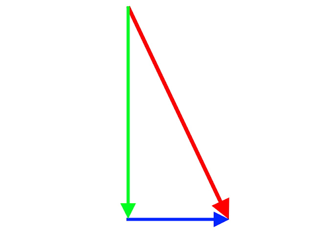
Now, consider just the window pressure. It’s an angled vector, but since vectors can be decomposed along each dimension, we can also represent it as its components along up/down (y) and front/back (x) axes:


When multiplied by area to give a force, we call the horizontal arrow “drag” (negative/backward) or “thrust” (positive/forward), and the vertical arrow “lift” (negative/up) or “downforce” (positive/down).* If I change the pressure acting on the window—say, by fitting a spoiler—it will change the resulting force that is created there, with the force always acting in the same direction as pressure, and that change will be proportional to the change in pressure which can also be represented by a vector (yes, just the difference between two pressures or forces can be represented by a vector!). The same is true on the base. I’ll estimate the pressure change on each surface by averaging both measurement locations from my testing and subtracting the initial pressure from the final pressure.
 
Next, I need an area in order to calculate force. I can approximate the rear window and base by measuring the outside dimensions of each, as well as the average angle of the window, and representing them as simple rectangles. Basically, I’m simplifying this:


…into this:


I measured an area of 1.04 m2 and 13.7° inclination for the window, and 1.20 m2 for the base.
 
Because I’m approximating base pressure acting on a vertical rectangle, no decomposition is needed; the resulting force acts horizontally so the simple equation F = pA holds. But the window is more complicated since it’s angled. Using trigonometry, I derived formulas for the change in drag and lift by dividing the window pressure into its components; the horizontal component is then added to the force change on the base:
…...where subscript “1” refers to the base and “2” to the window, and phi is the average angle of the window from horizontal.
 
All right, now I’ve got everything I need to estimate the changes from fitting each spoiler. Negative numbers represent an increase in drag or higher lift, and positive numbers a decrease in drag or lower lift:
 

Spoiler Type

Change in Drag (N)

Change in Lift (N)

Gurney flap (both)

-7

+20

10° spoiler

-10

+10

20° spoiler

-5

+30

20° slotted spoiler

-5

+30

30° spoiler

-20

+30

 
Aha! Now some trends become clear that weren’t before. As the large spoiler’s angle increases, the increase in pressure may offset the drag increase from the base to an inflection point (around 20°) after which drag increases with spoiler angle. The small Gurney flap is probably better than the 10° spoiler, in terms of its effect on both lift and drag. And the slot doesn't appear to make a difference in the spoiler's effect on body panel pressures, although I don't know if it changes the force acting on the spoiler itself.
 
However, take all these with a healthy dose of skepticism. I had to make a lot of simplifying assumptions, and I only did this so I could compare the different spoilers and try to get an idea of which might be better for my purposes in the future. There may be interactions between any one spoiler design and another part of the body I didn't measure. The pressure across the panels I did measure may vary considerably from the spots where I placed the taps. I’m not able to account for the drag or lift of the spoilers themselves, and I haven’t verified any of these calculations by, say, measuring lift directly.
 
That said, stay tuned because in the future I'll try and measure changes in drag and lift directly. That should give me a good idea of whether this method is useful or not by corroborating what I calculated here or throwing it all out the window.
 
[*Note that I am using aeronautical convention, with positive vertical axis pointing downward].

Comments

Popular Posts

Coastdown Testing Revisited

Tuft Testing: A How-To Manual

A Practical Guide to Aerodynamic Modification