Modern
car shapes are approaching the limits of low drag, were it not for details such
as wheels, drivelines, suspensions, brakes, and cooling. This is good news for
home modifiers. If your starting point is a car with a good basic shape, such
as a Prius (as opposed to a car with a horrible basic shape, like my
pickup), things like wheel drag and cooling system drag are likely responsible
for a larger fraction of overall aerodynamic drag. These areas, then, are good
targets for drag reduction. In the next few posts, I’ll address the cooling
system.
Cooling
airflow is responsible for a significant drag fraction on modern cars. Yes,
even on EVs! EVs require more cooling than a lot of people think; they are very
much not "no cooling air necessary," as some online aerodynamics
aficionados seem to think (and we’ll see later on why it might be beneficial to
use a large heat exchanger even on an EV).
 |
| This ZR1 cutaway shows two of its many heat exchangers; unlike most cars, the central exchanger here is fully ducted, to an exit in the center of the hood. |
Cooling
Package
Most
people think of the engine heat exchanger ("radiator"—a misnomer, as the primary
mechanism of energy transfer from the hot liquid coolant to the air passing
through it is not radiation) as the "cooling package." This is
incomplete: modern cars typically have multiple heat exchangers.
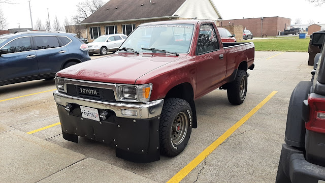
 |
| My truck, which turned 35 last year, has just one heat exchanger—this is fairly typical of older cars with no air conditioning system, no added transmission or engine oil coolers, and no turbos. Also typical is the lack of any ducting or closeout panels around the exchanger. |
 |
| My Prius, on the other hand, has a cooling package that consists of three heat exchangers: one for the engine, one for the inverter, and one for air conditioning. Many newer cars have even more! |
 |
| For example, the current Tundra Hybrid has three (engine, inverter, AC) plus two more exchangers for the twin turbos. |
Heat
exchangers also don’t operate in isolation from other components; they need
airflow. The paths of airflow into the heat exchanger, through the heat
exchanger, and out of the heat exchanger are therefore all part of the cooling
package.
Performance
Goals
Generally,
the design of cooling systems must take place with two goals or constraints in
mind. First, we have to meet the cooling requirement—whatever that is! Your
car has a cooling system designed for extremes of operation in its expected environments,
possibly globally (depending on what markets it’s sold in); you don’t
necessarily need the same cooling capacity, or you may need more e.g. if you
track your car at high sustained speeds in hot weather.
For
example, the worst-case conditions my car has seen occurred driving out of
Vernal UT over US 191 into Wyoming in July heat. In those conditions (100°F at
6,000 ft ASL), air density is about 19% lower
than it is on a summer day where I live, and since I road trip out West and across
the Rockies most summers and am likely to encounter that again, I want to
ensure I’m maintaining the cooling capacity to handle it. On that trip,
climbing up the Uinta Mountains, I could watch coolant temperature tick upward
if the car’s speed dropped too low due to insufficient mass flow.
 |
| My family settled in Vernal at the end of the nineteenth century, and several generations are buried in the city cemetery there including my great-great-grandmother, a Welsh immigrant who pulled a handcart across the Great Plains in 1856. |
We
can model mass flow per unit capture area at constant speed as a function of temperature
to see how it behaves. Here, I’ve plotted this at 65 mph and various altitudes
up to 6,000 ft ASL (the highest most of us in the US ever drive):

Notice
something curious: as temperatures drop, we get more mass flow through the
cooling system precisely when we don’t need it, and less mass flow in hot
weather when we need more (because cooling capacity is dependent on both mass
flow rate and the temperature difference between air and coolant; as one goes
down, the other needs to go up to maintain cooling capacity). Instead, what we
get is increased temperature difference and mass flow during the winter
and the opposite in summer—a fundamental challenge in designing car cooling
systems. Because of this, they have to be sized and designed for the worst-case
summer scenario (low density, small temperature difference, high engine load, low
speed).
Second,
we want to minimize drag from the cooling system, which can be a significant
fraction of overall aerodynamic drag on modern cars. This includes both reducing
momentum loss through the cooling system (internal drag) and minimizing external
effects on the vehicle flow field at the cooling system air inlet and exit
(interference drag).
Cooling
System Components
Before
we go on, let’s divide the cooling system and its components into states or
locations. I will identify these as follows:
Freestream:
State a (ambient)
Grill:
State a to State 1
Diffuser:
State 1 to State 2
Heat
exchanger core(s): State 2 to State 3
Fan(s):
State 3 to State 4
Nozzle/outlet:
State 4 to State e (exit)
Analysis
and Procedure
Now
that we have identified each state, we can step through the cooling system and
analyze each component. Energy loss or dissipation through the cooling system
can be measured by the loss in total pressure (p0) at
each station, and the efficiency of the cooling system as a whole can be calculated from the difference in total pressure in the ambient and at the cooling airflow outlet (as we'll see in a few posts).
I’m basing my analysis on the work of Hoerner, Barnard, Wolf, and others as well as adapting the methods I was taught to analyze
airbreathing propulsion systems in aerospace i.e. jet engines, which struck me
one day in class as bearing a lot of similarity to cooling systems in cars: air
is ingested, heat is added, and then it is expelled (jet engines do a bit more—namely,
compression to raise total pressure before combustion and work extraction via a
turbine to power the compressor—but fundamentally the process is similar). As
the instructor in that class said on many occasions, nomenclature and equations
differ among sources but they all characterize the same physics; if my method
doesn’t make sense to you, feel free to use another. However, I find the
analysis techniques I will use here most familiar and intuitive, and I will try
and relate everything clearly to the physical working of the cooling system at
each step. I’ll introduce models—some mathematical, some physical—that you can
work through or build yourself. And we’ll analyze model outputs to see what
they tell us about improving your car’s cooling system performance. Then, we
can use these models to determine what to measure and interpret what the
measurement data tell us about the cooling system performance of your own car.
 |
| For example, here’s a simple model of a ducted heat exchanger you can make yourself using an air filter. We’ll see in a few posts what this shows us about the flow through your car’s cooling system. |
Where to start? Your first step should be to measure your cooling system’s
performance as is, otherwise you will be shooting in the dark trying to modify
it. So, we’ll begin there. I'll step through each component (grill, diffuser, heat exchangers, fans, outlet) and develop the theory behind each that will allow us to identify what parameters we should measure and how to interpret results. Then, I'll have a post on the model duct above. Finally, I'll develop a set of recommendations for modifying your car's cooling system: what to measure and what sorts of changes to investigate. Along with that, I'll go through the process on my own car to see if I can improve its cooling system performance.
Next time: we'll begin at the beginning, with grills and diffusers.


Comments
Post a Comment